Services

Emergency Call - 24/7

MATERIAL PROPERTIES

IMPACT STRENGHT

PE is a relatively ductile thermoplastic which exhibits a very high impact strength compared to other thermoplastic such as uPVC particularly at moderate low tem­peratures.

PE is unique by retaining high levels of impact strength at sub-zero temperatures and is significantly superior to most other thermoplastics in this respect.

TOXICITY AND TAINT

PE is free from heavy metal stabilisers used in the processing of many other thermo­plastics materials and therefore there are no toxic heavy metal substances present which can be leached out. Jahaplast PE has been safely used for many years with potable water, grade 1 distilled water for medical use, renal dialysis fluid and many food and beverages.

Jahaplast PE piping system is conforms to SNI 06-4829. Suitability of plumbing and water distribution systems products for con­tact with potable water.


PE is regarded as taint free and has been used for conveying beer, soft drinks, cara­mel, wines, sauces, chocolates, custard cream and other similar products. It is rec­ommended however that food and drink manufacturers should test for taste tainting on their own product before installation commences.

BIOLOGICAL RESISTANCE

PE is not subject to biological attack through the action or micro-organisms such as bacteria, fungi or spores.

Termites and rodents have been known to penetrate thin walled soft PE pipes, however Jahaplast PE Fittings are more resistant due to the higher level of material hardness and thick wall sections.

ABRASION RESISTANCE

PE piping system have been long successfully employed in applications where abrasion resistance is the prime consideration. The conveying of slurries in the mining industry is a typical example where PE has been demonstrated to outlast steel pipes previously employed.

The chemical resistance of PE combined with impact resistance makes it an ideal choice for those corrosive erosive environments. It is these conditions which lead to reduced life of metal pipe systems.


Jahaplast engineers have the experience to advise on the suitability of PE for slurry of abrasive applications.

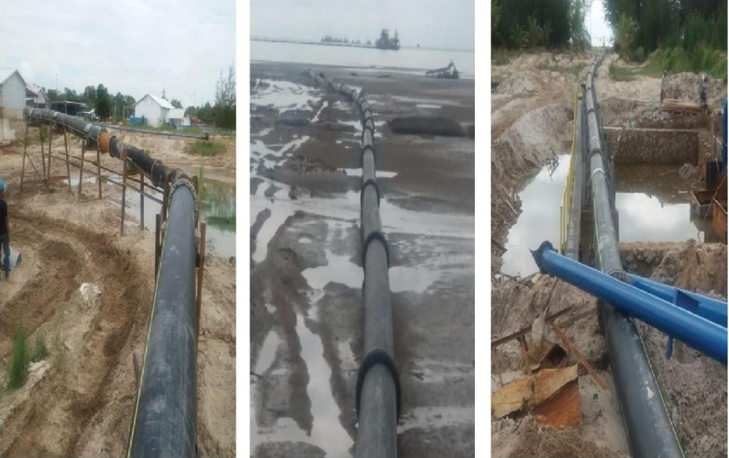
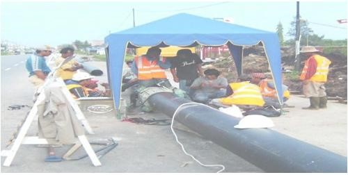
Jahaplast PE Piping Line DN630mm PN12.5 

at PT. Timah with high abrasion  application

WEATHERING

Weathering of plastics occurs by a process of surface degradation due to the combined effect of ultra violet radiation, increased temperature and moisture when pipes are stored in exposed locations.

Jahaplast PE Fittings contain antioxidants, stabilizers and pigments to provide protection from ultra violet radiation.

Black PE Fittings contain carbon black pigments which act both as a pigment and as an ultra violet radiation stabilizer and these pipes require no additional protection for external storage.

Other colour PE such as yellow or blue systems do not possess the stability as the black pig­ment systems. The period of external storage should be limited to one year.

CHEMICAL RESISTANCE DATA

The information given on the following pages based on the recommendation of the manu­facturers of the polymers and field experience or subsequent tests by Raw Material Suppli­er.

The data is based on the exposure on tensile bars to the environment to the environment, and associated weight changes, tensile strength, elongation determination. These results are augmented by environmental stress cracking tests.

Specific data on industrial chemical applications of PE can be given by the PE100 organi­sation. Such enquiries are invited to applications not shown here.

Under no circumstances is it to be assumed that a mixture of individually acceptable chemicals may be safely used with PE or any other product.

Absence of notation indicates substance has not been tasted.

Unless stated, all concentration are 100%, or saturated aqueous solution. Reference of saturated solutions is based on 20°C

CHEMICAL

RESISTANCE

Weak acids

Good resistance

Strong acid

Limited Resistance

Weak alkalies

Good resistance

Strong alkalies

Good resistance

Agressive soils

Good resistance

Metal soils

Good resistance

Sea soils

Good resistance

Aromatic Hydrocarbons

Poor resistance

Organic Solvents

Poor Resistance

PE Quick Reference Chemical Resistance

RESISTANCE KEY INFORMATION

1.                Resistant: Little or not attack

2.                Conditional resistance:

Some attack, however may still be suitable when used with a higher pipe class or

reduced service life. Further consultations with Jahaplast are recommended.

3.                Not recommended:

Little or no resistance. Not suitable for use with PE pipe.

S.S Saturated Solution

It should be noted that production of substances may involve process upsets which sub­ject piping systems to varying pressures, temperatures and chemicals. It is the design engineer’s responsibility to assess the materials and exposure conditions. It is likely that the positive characteristics of Jahaplast PE make it a more suitable choice than other materi­als.

PRESSURE CONSIDERATIONS

STATIC STRESSES

The resistance of PE pipe to hydrostatic pressure is determined by:

1.              The ratio between the diameter and wall thickness.

2.              The hydrostatic design stress (Sigma value) for the particular grade of PE.

3.              The duration of applied pressure over the pipeline lifetime.

4.              The pipe material service temperature.

Jahaplast fittings manufactured are designed for hydrostatic pressure conditions using 

the Barlow formula as follows:

Where

T        = minimum wall thickness (m)

P        = working pressure (MPa)

D       = maximum OD (mm)

S         = design hoop stress (6.3 MPa) (50yr©20°C)

The design of PE pressure piping system has been based on static working pressures con­tinuously operating at the maximum level for the entire lifetime of the pipeline.

PIPE ANCHORS

Pipe anchor should be provided in installations where the thermal expansion is a consid­eration.

Anchors ensure that pipe movement occurs in controlled and predictable manner.

In addition, pipe anchors will absorbs axial pipe pressure thrust in those systems fitted with expansion joints.

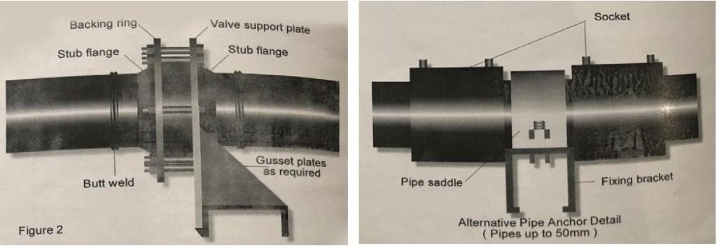
Where possible, a flanged pipe connection may be used as an anchor point by the use of a valve support in lieu of one of the backing rings. Refer to Fig 2. An alternative

method for pipe diameters up to 50mm is shown in Fig 3.

Anchor points located at mid length of a straight section need not be robust as those associated with expansion compensators which must be able to withstand the total pipe thrust plus frictional resistance to movement.


Note; Under no circumstances can a tightened pipe clip be used as anchor. The action of tightening the clip imposes a crushing load on the pipe which may cause pipe failure.


BUTT JOINTING PROCEDURE

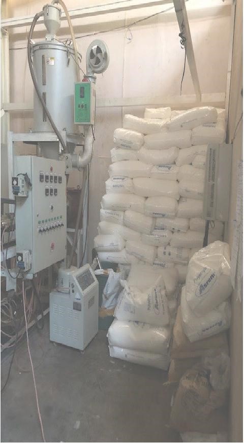
The following equipment and services are needed:

Constant 220v output electricity supply. Buff-fusion machine, complete with clamps and hydraulic activation unit. Electricity heated mirror plate with tem­perature indicator.

Planning tool.

Timer

Pipe supports

Pipe cutter or fine toothed saw

Cleaning material (paper or clean cloth)

1.  Read the operating instructions for the welding machines and check all equip­ment is undamaged and in good working order. Inspect and clean the heating mirror, removing any residue from previous weld. Make a dummy weld to ensure all particu­late is removed from the heater plate.

2.  Switch on and retain the plate inside the thermally insulated protective case. Adjust the control temperature to 205 -/+ 5o C.

3. Clean ends of components to be joined, inside and out.

4. Fully open the carriage in the machine and place components in clamps with 25 to 30mm protruding.

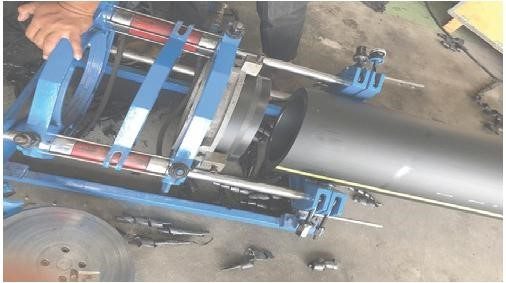
5. Align and level components in clamps using support rollers if necessary. Rotate as necessary to align orientation markings and tighten clamps.

6.  Positions the plane in the machine.

7.  Switch on the place and close the car­riage slowly so that ends to be welded come into contact with the rotating blades. Note the planning pressure shown on the machine data plate and holding this on until continuous shavings are cut from the ends of both jointing surfaces. Leave the paner switched on and rotating while pressure is released and the carriage withdrawn.

8.  Remove the planer, taking care not to touch the planed surfaces.

9.  Remove shavings from the machine and component ends, again taking care to avoid contact with planed surfaces.

10.      Check both surfaces are completely planed. If they are not, repeat steps 6 to 9.

11.Close the carriage and check that no visible gap exists between ends to be joined.

12.    Minimise pipe end mismatch (maximum 10% of pipe wall thickness) by adjusting clamps or pipe supports or by rotating pipe or combination of both operations.

13.    If such adjustment is necessary, repeat operations 6 to 12.

14.    Close the carriage and note the drag pressure which is necessary to move the pipes and/or fittings using the hydraulic system.

15. Consult the welding machine instruc­tions for the fusion pressure recommended by the machine manufacturer for the size of components to be welded. Add the respective pressure to the drag pressure to determine the ‘applied pressure’ during welding.

16. Remove the heating plate from the protective cover. Check again that it is clean and undamaged. Check that the temperature is 205 -/+ 5 C .

17. Place the heating plate in the machine and close the carriage so that surfaces to be joined touch the plate. Apply the pressure previously determined in 15.

18. Maintain the applied pressure until the pipe begins to melt and uniform bead of about 2mm is formed on each end.

19. Release the pressure but do not move the carriage. Keep the ends in contact with the plate for the time recommended by the machine manufacturer for the size of component to be welded. Timing starts from when the pressure is released.

20. When soak time is completed, open the carriage and remove the heated plate ­tapping as necessary to release it. Be care­ful not to touch the melted surfaces.

21. Quickly close the carriage (within 5 sec­onds of removing the plate). Hold the surfaces together at applied pressure.

22. Compensate for any instability on applied pressure and when stable, main­tain the pressure for the entire cooling times, as follows :

90mm to 110mm – 10 minutes

125mm to 200mm – 20 minutes

225mm to 315mm – 30 minutes 

23. The welded assembly can now be removed from the machine but not han­dled for a further 10 minutes.

24. Examine the butt-weld for cleanliness and uniformity. Check that
the bead width is within the following bands:

90mm to 180mm – 7 to 12mm

200mm to 315mm – 9 to 15mm

25. If it is necessary to remove the internal bead from a but weld. This can be done using a special tool. Contact Jahaplast for further information.
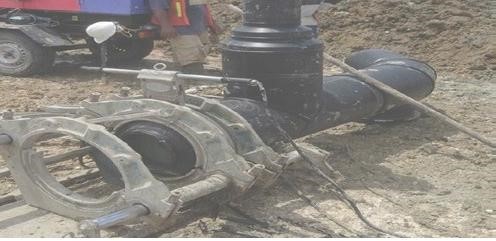
REPAIRS

The repair of buried pipeline using but-welding techniques can be difficult and expensive due to the problem of intro­ducing the butt-welding machine into the trench. Furthermore, axial movement of pipes needed to make the weld is rarely possible.


If only but-welding is available, the only efficient method is to incorporate a flanged spool piece which can be made above ground and only requires flanges to be attached to the pipe in the trench. A far more efficient and cost-effective method is to electro fuse

a new section of pipe into place following the procedure.

TAPPING AND SERVICE CONNECTIONS


Buff-fusion is not generally used for service size pipework and socket fusion is rarely satisfactory either. The buff-welding of tapping saddles to mains pipe is difficult to control and does not produce consistently satisfactory joints. It is recommended, therefore that service connections to mains be affected using

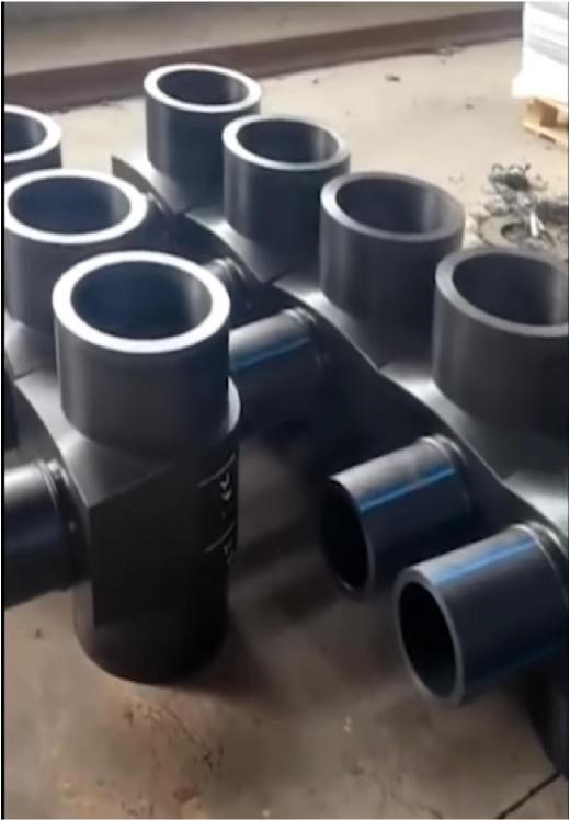
PRODUCT PT. JAHAPLAST
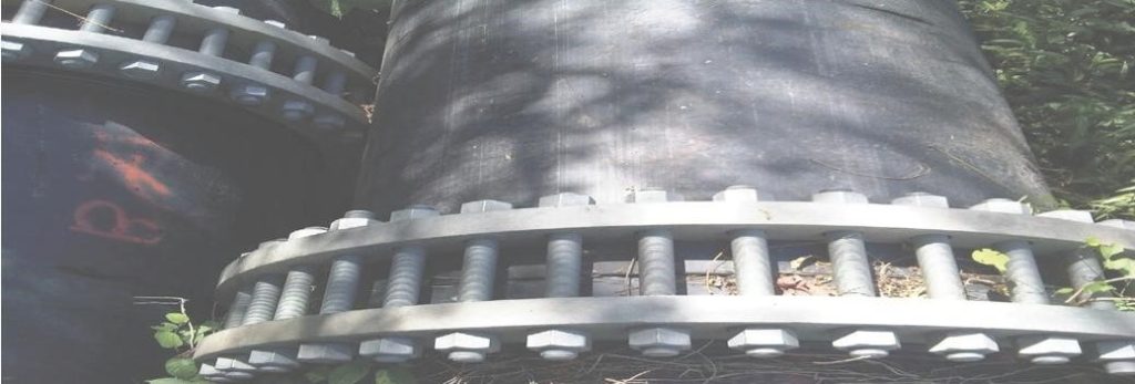
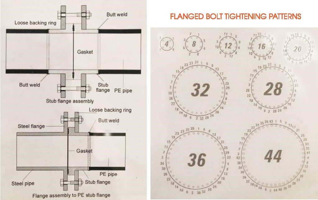
STUB FLANGED JOINTS

Stub flange joints are available in sizes 20mm to 1000mm.

Stub flanges are the preferred style as they offer a more economical fitting and are easier to install than the full face style. Stub flange assemblies  have the same pressure rating as full face flanges assemblies. Gaskets must be used with flanges. PE Stub flange assemblies may be bolted directly to other flanged pipe systems of the same flange drilling i.e. ANSI 150, Table E etc. Gasket must be used at the joints. The adjacent drawing illustrates a cross section of a PE stub flange to standard full face steel flange joint. Flange bolt torque values are for PE Fittings need not be as high as those commonly used on steel pipe systems. Higher torque values may result in distortion of the flange face. The torque values represent a nut and bolt that is suitably lubricated. Standard butterfly valves may be placed between PE stub flanges or full face flange assemblies without modification. Valves should be checked for full and free movement prior to final tightening of flange bolts.


Pipe

Size (mm)

Bolt Size

Recommended Torque
(NM)

No. per Flange

20

M12 x 50

10

4

25

M12 x SO

14

4

32

M12 x 50

13

4

50

M16 x 65

22

4

60

M16 x 65

25

4

80

M16 x 70

33

4

100

M16 x 80

25

8

125

M16 x 90

34

8

150

M20 x 90

42

8

200

M20 x 100

63

8

250

M20 x 130

80

12

280

M20 x 150

108

12

315

M20 x 150

74

12

355

M24 x 160

133

12

400

M24 x 170

163

12

450

M24 x 180

157

16

500

M24 x 190

185

16

560

M27 x 230

191

16

630

M27 x 240

190

16


THREADED CONNECTION:

Jahaplast manufacture a range of male and female BSP threaded adaptors up to 100mm (4″). 

When threading use a sharp die and cut full thread depths. Without lubricant in one operation. 

All threaded fittings are rated 1200kPa at 20C. 

For high pressure installations it is preferable to use adaptors or fittings with male PE threads in preference to female threaded fittings. 

Composite unions, available in male and female threaded configurations up to 50mm are recommended for joining PE pipe to metal threads particularly in systems subject to thermal cycling. 

Tightening should only be done by hand with a maximum of an extra quarter turn with a pipe wrench. There is offen a tendency to overtighten threads however this only causes distortion and leaks. 

If a threaded connection is leaking disassemble the thread and if not damaged remake the connection taking care not to overtighten. PTFE tape is the recommended thread sealant.

Quick Service On Emergency Call - 24/7